
PCB Short debugging

A terrible state of affairs
Have you ever been in the situation where you receive an assembled PCB from your manufacturing partner and start your power-up test to find a short circuit on the board? If the short is between signal tracks it can be a relatively simple process to locate the short – where do the 2 nets meet at a component? Do they run next to each other? Using your CAD tool to highlight the 2 tracks and looking at intersections can be useful, but its really unlikely that you will be able to locate such a short with a standard DMM (Digital Multi-Meter) because the track resistance will be very low.
What happens if the short is intrinsic in the PCB – in other words a bare board manufacturing fault?
What happens if the short is below a component?
The situation is compounded if the short is between a signal track and ground plane, or worse, a power plane and ground plane.
How could you tackle such a short?
Baby steps
When tackling such a short, the following steps can be useful:
- Does the issue exist on one board or the whole batch
- Does the issue exist on a bare, unpopulated board?
Understanding if the issue is a PCB bare board manufacturing fault or and assembly fault is important, the route forward will be different in each case.
If the bare board is short-free and the short exists on assembled boards only, the fault could be due to:
- Misaligned components – SMD pads not completely aligned with the PCB pads, solder bridges on parts with thermal pads.
- Parts loaded with incorrect polarity – Look for ICs, diodes, and polarised capacitors which have been rotated. If you have any tantalum capacitors in the design, often the +ve. is marked, not the -ve. like an electrolytic capacitor.
Tools of the trade
As mentioned earlier, locating a short with a DMM is almost impossible. “Beeper mode” will indicate that you have a short, but it is very unlikely that you will be able to work out where on the PCB the short is using this method.
A low-ohm (milli-ohm) meter is a better bet, there are cost effective options available, but the biggest issue is getting a good-quality connection to the tracks so that the probe to track resistance is less significant than the track resistance that you are measuring.
In 40 years in this industry there has only been 1 tool which will truly help locate a short – The Polar Toneohm 950.
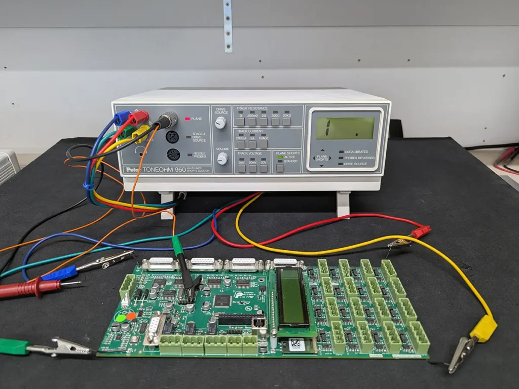
The Toneohm, set up with a PCB to test
It has a number of modes:
- A Milli-ohm meter coupled to a tone generator which “Squeeks” the resistance between the probes
- A hall effect “Current tracer”. A current (generated by the test equipment) is connected across the short and this current is “traced” using the Hall probe. In conjunction with the PCB layout, a short between traces can le located easily
- A plane short location – this is truly remarkable. 4 wires are connected to the corners of the plane with the short. A wire is attached to the trace (on other plane) which is shorted. A contact probe is then used to trace the plane or the trace. 4 “arrow” LED’s on the equipment then stipulate the location of the short, with respect to the probe – pure genius!
Cubik EPS has a Toneohm 950, ours is dated 2000 and is powered by a Z80 processor!
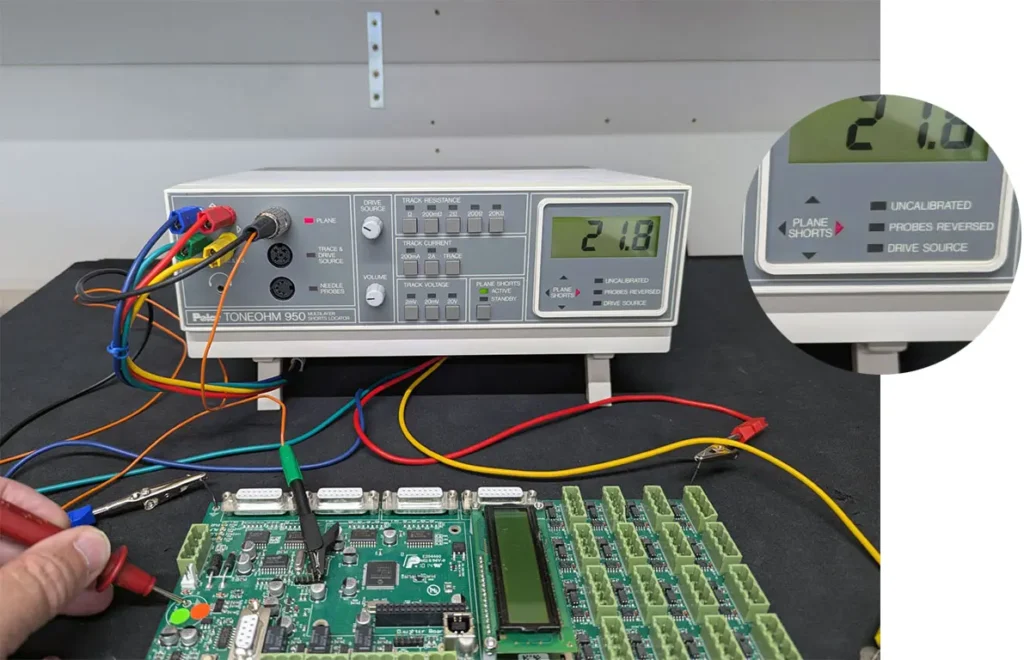
The short is located to the right of the probe, signified by the arrow LED’s
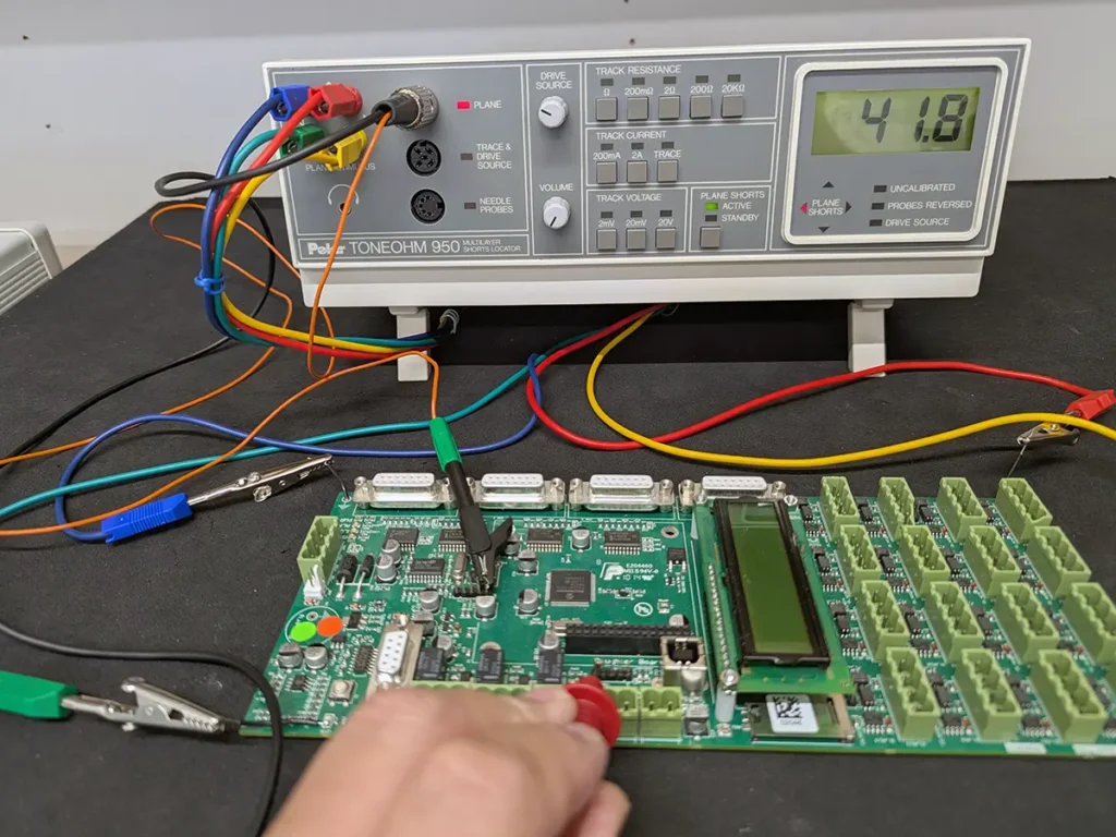
The short is located to the left of the probe.
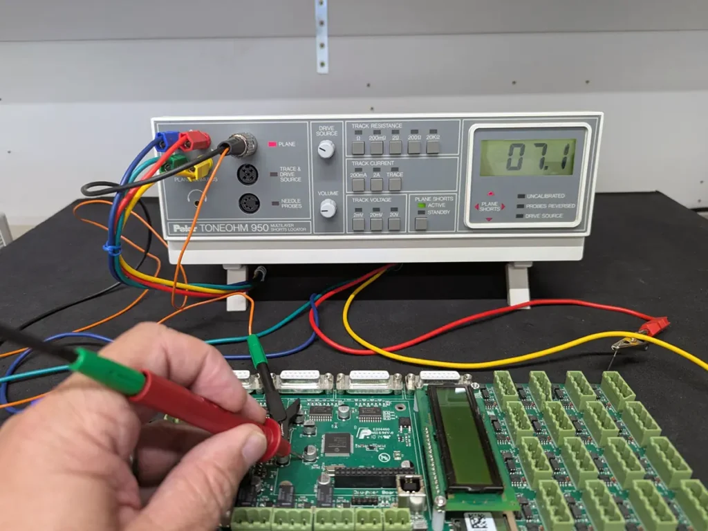
Bingo! The short is located at the location of the probe
So, where does Cubik EPS fit in?
PCB shorts are a pain. They are difficult and time consuming to resolve. If you have a PCB with such an issue, Cubik EPS would be happy to investigate and clear the fault, if possible, using our trusty Toneohm.
If you are interested in Cubik EPS helping, please drop us an email or give us a call.
Contact Paul for a free 30-minute consultancy